10+ igbt block diagram
Such a thin semiconductor material can have kV voltage and hundreds of amperes of current on and off its amazing. The JFET represents the constriction of current between any two neighboring IGBT cells.

Wind Energy Application Examples Semikron
In this figure AC power source is rectified into DC by rectifier diodes and then reversely converted into AC by switching at high frequency the IGBT of the inverter portion thereby achieving variable speed driving of the motor.

. The control block provides all digital signals to implement the right motor driving strategy. One is an optocoupler which electrically isolates signals. The main task of this block is to accept user commands and boardmotor configuration parameters.
Silicon Carbide SiC MOSFETs. I am a student of Electrical Electronics Engg. A Lumped-Charge Approach Based.
Each IGBT and thus can minimize the possibility of severe damage to the IGBT. A circuit symbol for the IGBT is shown in Figure 3. Help if anyone could explain me the working of an IGBT tester preferably with a block diagram.
Figure 7 Block diagram of a test with ideal driver 2. A gate drive circuit is mainly composed of three sections. Nov 8 2003 2.
I have been given IGBT Tester as my. Data Sheet 5 Rev. The figure below is a block diagram which outlines a gate drive circuit.
This is why the price of high-power semiconductor devices is so very expensive. 31 2016-04-05 2ED020I12FA Dual IGBT Driver IC Block Diagram 36 2 Block Diagram Figure 1 Block Diagram 2ED020I12FA GND1 INHS INHS-RDYHS. Therefore the entire delay time is attributed to the IGBT device itself.
IGBT is a short form of Insulated Gate Bipolar Transistor combination of Bipolar Junction Transistor BJT and Metal oxide Field effect transistor MOS-FETIts is a semiconductor device used for switching related applications. An Insulated Gate Bipolar Transistor IGBT is a device that switches power on and off between a collector and emitter by controlling the voltage between the gate and emitter in the same way as MOSFET. Download scientific diagram IGBT block voltage non-punch through NPT condition compared to punch through PT condition at turn-off transient.
The STM3210B-EVAL ST demonstration board based on an STM32 microcontroller can be connected to the STEVAL-IHM027V1 thanks to the. The upper copper layer interconnection of IGBT chip Diode chip and DBC is generally realized by bonding wires. Post by raju I am a student of Electrical Electronics Engg.
They also protect against arm short-circuits1 The UV protection circuit is in all of the IGBT drive circuits. HEVEV Traction Inverter Design Guide Using Isolated IGBT and SiC Gate Drivers Figure 4. Our Interactive Block Diagram tool is as easy to use as 1 2 3.
Articles provide different examples covering tele-monitoring systems in medical setups 10 accurate measurement of the absolute thermoelectric power of. Chapter 10 EMC Design of IGBT Module 10-7 Fig. With a vast variety of diagrams to choose from you are able to experience the full breadth of the ON Semiconductor product portfolio in a clear concise mapped out system level block diagram.
Thyristor does not latch up which will lead to the IGBT latchup. IPM Block Diagrams3-13 5. 10-9 shows the block diagram of a typical power drive system.
Data Sheets 14 Videos 11 White. Toshiba IGBT can be used in a wide range of applications from home appliances to infrastructure equipment like trains. Delay most likely for oversized drivers.
Block diagram of IGBT based DC Drive. Junction J2 are reversed biased. When collector is made positive with respect to emitter IGBT gets forward biased.
Timing Charts3-21 Chapter 4 Examples of Application Circuits 1. The collector terminal of the NPN transistor is connected to the base terminal of the PNP via JFET transistor. 6 10 IGBT Driver IGBT Module.
Help if anyone could explain me the working of an IGBT tester preferably with a block diagram. The working principle of IGBT is based on the biasing of Gate to Emitter terminals and Collector to Emitter terminals. Another is an interface circuit which receives and.
Based on the basic structure of the IGBT a simple circuit can be drawn using PNP and NPN Transistors JFET OSFET that is shown in the below figure. The three legs of the inverter convert the DC. Figure 7 depicts the block diagram of the test setup.
I am a student of Electrical Electronics Engg. I have been given IGBT Tester as my final year project at SIEMENS. What is the maximum turn-off delay time when the threshold voltage of the IGBT is at its minimum in the datasheet.
Commonly used bonding wires are aluminum wire. With no voltage between Gate and Emitter two junctions between n- region p region ie. It would be of great help if anyone could explain me the working of an IGBT tester preferably with a block diagram.
It supports most of the voltage and allows the MOSFET to be a low voltage type and consequently have a low RDSon value. This circuit monitors the Vcc supply voltage. I needed some information on how to exactly an IGBT is tested.
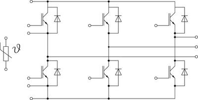
As IGBT is a combination of MOSFET and Transistor it has advantages of the both transistors and MOSFETMOSFET has. High-Voltage Traction Inverter Block Diagram A closer look at the inverter shown in Figure 5 reveals six total semiconductor power switching devices with a gate driver to amplify the PWM signal from the MCU. These transistors signify the parasitic thyristor which.
It has three terminals. I have been given IGBT Tester as my. Circuit Diagram of an IGBT.
Frank Bemelman 2003-11-08 132632 UTC.

How To Make Igbt Driver Circuit Mosfet Driver Circuit Youtube Circuit Diagram Circuit Drivers

What Is Igbt Structure Explained And Disassembled

No Need For External Sensors In New Inverter Generations Semikron

Wind Energy Application Examples Semikron

Skiip 02ac066v1 Semikron

The Schematic Diagram Of The Induction Heater With Igbt S Induction Heating Circuit Diagram Induction

How To Make Simple Inverter Circuit Diagram Within 5 Minutes Circuit Diagram Electronic Circuit Projects Electronics Basics

Update 3 How To Build The Simplest Dc Motor Speed Controller Using Mosfet And Potentiometer Youtube Motor Speed Circuit Diagram Diy Electronics
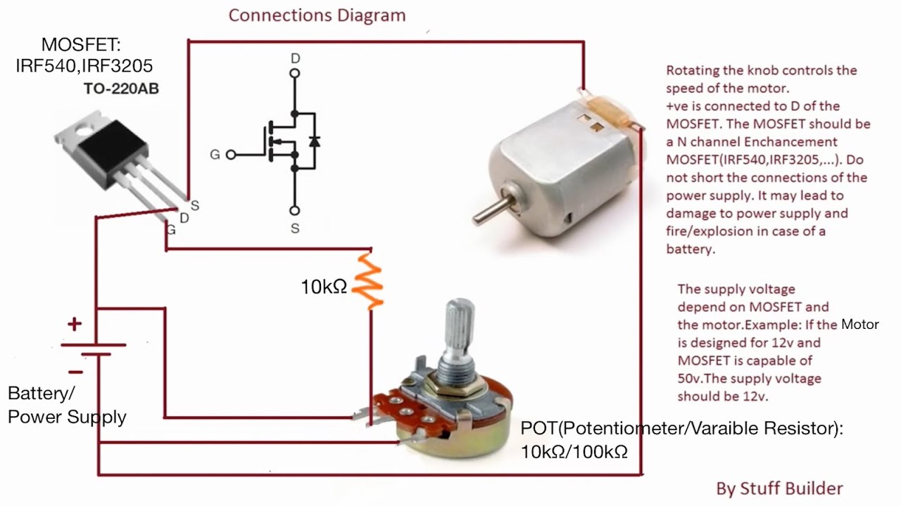
Update 3 How To Build The Simplest Dc Motor Speed Controller Using Mosfet And Potentiometer Youtube Motor Speed Circuit Diagram Diy Electronics

Igbt Switching With Cable Load Semikron

Capacitor Circuits Capacitor In Series Parallel Ac Circuits Circuit Electronics Circuit Capacitor
Semix305gd07e4 Semikron
How Does A Driver Circuit Work For An Igbt Quora

What Is Igbt Structure Explained And Disassembled
Igbt Insulated Gate Bipolar Transistor Electronic Circuit Projects Electronics Basics Transistors

Igbt Switching With Cable Load Semikron

Igbt Driver For 2 Level And 3 Level Industrial Applications With Enhanced Isolation Capability For Dc Voltages Of Up To 1500v Semikron